Fitting Instructions - Flywheel and Diaphragm Clutch
Fitting Instructions - Part Number RH7199KT
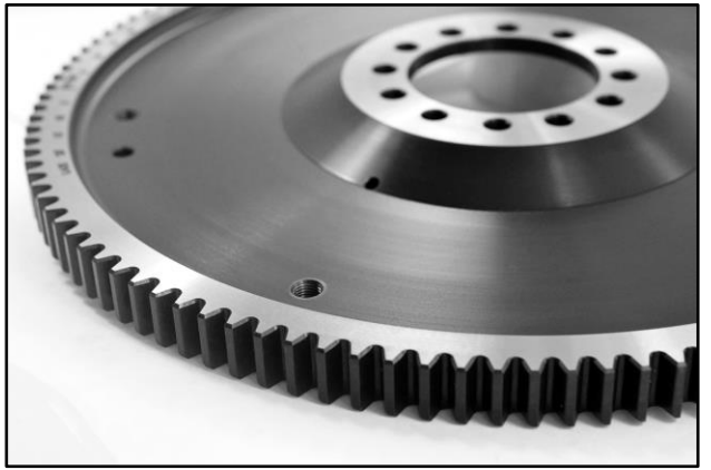
The Prestige Parts replacement diaphragm-type clutch uses a completely new mechanism, designed for use with modern friction lining materials, and has been developed with the technical input of renowned Rolls-Royce and Bentley specialists. The flywheel has been specially designed and incorporates timing marks for both right-hand and left-hand drive cars. The mating surface for the friction lining has been ground to an 8-micron surface finish (about the same as a glass surface) for the smoothest possible take-up.
RH7199KIT consists of the following components:
- Flywheel
- Diaphragm Clutch
- Drive Plate
- Flywheel Bolts (3/8” UNF, x12)
- Flywheel Aero Nuts (3/8” UNF, x12)
- Flywheel Spigot Bearing
- Clutch Release Bearing
- Bolts (1” x 3/8” UNF, x6)
- Spring Washers (x6)
- Steel Dowel (20 x 8 mm, x3)
- Wooden Dowel Rear Mains Oil Seals (x2)
- Engine Sump Gasket
- Front Cover Gasket


Remove the Gearbox:
- Disconnect the Speedometer drive, and the flexible oil pipe from the rear of the gearbox.
- Disconnect the oil damper control rod.
- Slacken the inner nuts only on the rear cups of the two rear gearbox torque reaction rubbers, remove the rubbers and then the torque reaction bracket. (Important: leave the outer nuts on the cups of the torque reaction rubbers undisturbed throughout).
- Remove tie bar complete with bracket and packing piece.
- Disconnect the centre universal joint on the propeller shaft. Disconnect the front propeller shaft from the gearbox & slide clear.
- Uncouple the gearchange lever and remove the selector shaft from the gearbox.
- Remove pull rods and drag linkages from the brake servo, slide the gearbox sideways and remove the servo motor from the driving shaft.
- Support the rear of the engine and slide the gearbox away. It may be necessary to destroy the crankshaft spigot bearing if the gearbox first motion shaft cannot be easily withdrawn from the bearing. A replacement spigot bearing is included in the kit.
Remove the Clutch from the casing:
- Remove bottom cover and turn flywheel until one of the three locked bolts retaining the friction plate to the flywheel is exposed. Remove the nut and bolt.
- Turn the flywheel to expose two of the remaining six nuts retaining the clutch to the flywheel. Slacken off and insert a spacer (a ¼” BSF nut will do). Remove bolts.
- Hold the clutch and turn the flywheel to bring the locking bolt hole to the lowest position and remove the clutch.
- Remove and discard original composite flywheel, flywheel bolts, flywheel nuts, original clutch and clutch bolts.
Remove the Engine Sump and Rear Main Bearing Housing from the Engine:
- Drain the oil from the engine and remove the engine sump.
- If fitting the clutch to the engine in situ, carefully cut away the front cover gasket, leaving the upper part intact. If the engine is out of the vehicle, the front cover may be removed, and the gasket replaced.
- Remove the Rear Main Bearing Cap, in order to access the crankshaft to flywheel bolts.
Fit the new diaphragm clutch assembly:
- Replace the small flywheel spigot and clutch release bearings.
- Press new flywheel bolts into the crankshaft flange.
- Mount the new one-piece flywheel and spigot bearing onto bolts (the flywheel will only fit in one position, due to a single hole being offset by 2°).
- Apply Loctite to threads, fit 12 x new Aero nuts and tighten in opposing radial sequence.
- Fit new clutch to flywheel with new bolts and spring washers, carefully aligning clutch centre plate with spigot bearing.
- Re-fit the engine sump, using the supplied sump and front cover gasket. If the front cover has not been removed, use the lower part of the gasket supplied and finish with gasket sealant.
- Re-assemble the gearbox and clutch, reversing steps (1) to (8) and (1) to (3).
Re-time the engine:
- Timing should take place with the engine cold.
- Set and lock the inlet valve on rocker no. 1 cylinder to 0.030” (0.76 mm).
- Turn the camshaft in the normal direction of motion until the inlet valve on the no. 1 cylinder just commences to open.
- Turn the crankshaft until the markings on the flywheel coincide with the timing pointer fixed on the housing. Important: please note that the flywheel is provided with two sets of timing marks: TDC (A) applies to right hand drive cars, while TDC (B) refers to left hand drive cars. Care must be taken to align the timing pointer with the appropriate set of timing marks.
- Bentley motorcars should be set to T.D.C., and Rolls-Royce models to the 10° late marking.
- Adjust the camshaft gear to mate with the crankshaft pinion. One tooth on the timing gear is equivalent to approximately 1.75” (44.5 mm) measured on the periphery of the flywheel. Hint: because the gear is attached to the camshaft with studs, it may be easier to remove the studs and temporarily replace them with setscrews, being careful to replace with the correct studs when the camshaft position has been set.
- Reset and lock the inlet valve rocker on no. 1 cylinder to a gap of 0.006” (0.15 mm).
Bleed the oil control system:
- Bleed by starting the engine and running slowly in top gear. Move the ride control lever to “Hard” and remove the air release plug from the rear shock absorber, replacing when a continuous flow of oil runs from the shock absorber.
- Repeat for the other rear shock absorber.
