Fitting Instructions - Replacement Actuating Toggle for Microswitches PM22514TG-X
Fitting Instructions - Replacement Actuating Toggle for Microswitches PM22514TG-X
PM22514TG-X has been added to the Prestige Parts® range in collaboration with Joschka RÖben.
Introduction
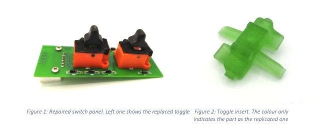
The toggles for the various microswitches in many Arnage and Silver Seraph series models tend to break, thus making the switch mechanically inoperable and hitherto requiring replacement of the entire switchpack, which is expensive and not always still available. This document will guide you through the removal and fitting of the toggle insert (Figure 2) for the window/lumbar switches and rear seat switchpack on the Bentley Arnage (98-09), Brooklands Coupe, Rolls-Royce Silver Seraph, Park Ward and 5th Gen Corniche.
The manual is applicable for switchpacks with the following part numbers:
PM22514PE - PM111715PB - PM111716PB - PP22409PE - PM108175PA - PW27090PB - PM108176PA - PW29501PB - PW29836PB - PW57141PA PW57140PA - PM107263PA


Preparation
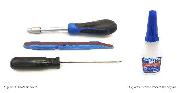
Figure 3 shows the tools needed for the job: A 5,5mm socket spanner, sanding stick (or a thin strip of sandpaper), a slotted screwdriver and superglue (e.g. Loctite 401, Figure 4). Furthermore, prepare a few grams of automotive grease for lubrication.


Installation
The following seven steps will guide you through the removal of the old and fitting of the new toggle insert. Follow every step and pay attention to detail!
Step 1 - Remove the switch (Figure 5) from the car following the instructions in the corresponding technical service directory. For these vehicles, you may use the erWin online system.


Remove brown top cover by loosening the four slotted screws, secured with M5.5 nuts on the reverse (Figure 6). Pay attention to the screw locking paint (yellow) being used.


Step 2 - After removing the top cover, insert the slotted screwdriver below the rocker switch and gently lever left/right to lift it up (Figure 7). The black plastic rocker switch is pressed into the translucent clear toggle insert. You will need to snap it off on purpose.


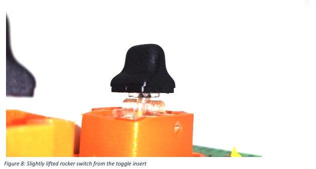
Gently rest the screwdriver on the orange case for the toggle insert. In order to prevent damage to the toggle case, a thin piece of metal to support the screwdriver may be used. With some gentle leverage, a gap will be visible below the translucent insert of the black rocker switch (Figure 8). With that being the case, the slotted screwdriver may also be inserted into this gap. Thirdly, the rocker switch can be jiggled by hand to release if from the toggle insert.


Step 3 - After removing the black rocker switch, sand down the bottom of it to remove any clear leftovers from the pressed insert (Figure 9). Use 240 and 600 grid sandpaper or a sanding stick. Furthermore, the top ring on the new toggle insert needs to be sanded back, otherwise the new rocker switch will stand a few millimetres to high.


Step 4 - As mentioned in Step 3, make sure that there is no gap between the black rocker switch and the new toggle insert (Figure 10). Sand or cut down the ring in the centre of the toggle insert as appropriate. The reason for the ring on the green replacement part is, if you somehow manage to remove the pressed clear insert (which is unlikely), you can use the ring of the new replacement to press it into the rocker switch, without using superglue.


Step 4 - As mentioned in Step 3, make sure that there is no gap between the black rocker switch and the new toggle insert (Figure 10). Sand or cut down the ring in the centre of the toggle insert as appropriate. The reason for the ring on the green replacement part is, if you somehow manage to remove the pressed clear insert (which is unlikely), you can use the ring of the new replacement to press it into the rocker switch, without using superglue.


Step 5 - Before inserting the new toggle insert, slot the pin and spring in to the bottom of the toggle (Figure 12). Also apply some grease to the mechanism and slot of the pin (Figure 13). The spring needs to be compressed while fitting the toggle insert. Ensure the pin does not slip out or bend. At the same time, you will need to widen the orange case by a few millimetres in order to fit the toggle insert. See Step 4, Figure 11, for details.


Step 6 - Figure 14 shows the repaired switch panel using the new replacement toggle insert. Note that the tactile feel may be different. This is caused by the microswitches below the toggle insert itself, not by the new replacement toggle.


Step 7 - Use the new dust seal provided (two are included, only one of which you will need, depending on the type of switchpack you are repairing) and reattach the brown top cover. Install switch panel (Figure 15) as described within the corresponding manuals.


Summary
Installation is finished – enjoy a fully functioning switch!
Contact
In case of further assistance is needed, either contact sales@introcar.com or the manufacturer J.Röben via joschka.roeben@jroeben.de
